

About Me
Hello there, I'm Daniel Strang! I'm a student in the Industrial Arts & Technology Teacher Education Program at RRC Polytech and U of Winnipeg.I am passionate about all things Industrial Arts and I love sharing that passion with my students. It's always incredible to see a student's eyes light up when they master a new skill or solve a problem they've been working on for a while.I am always trying to improve my craft, from trying a cool technique I saw on YouTube, to taking a course on a discipline I've never encountered before. I spend most of my making time woodworking, 3D printing, and working on graphics projects, but I try to spend some time in the worlds of electronics and metalworking too.Outside of teaching, I love getting outside any way I can. From canoe trips to winter trekking to scuba diving, I'm up for all of it!
Project Blog
Here's a space for me to ramble about projects that I've been working on!


Gallery
For the visual learners in the crowd, here are some photos of my projects, as well as some examples of my photography.

This section isn't quite done. Check back soon!
Lost PLA Brass Casting
May 1, 2021
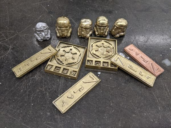
Lost wax casting has been around in schools for a while. At the college we still use it to make our grad rings in fourth year. After using the CNC machines at the college, I was worried that our rings may not turn out very well. I had heard that 3D printed PLA could also work in the casting process, and I figured that would be more reliable than the CNCs. Once I decided to try this, I had to figure out what to try to create. I have a pretty big coin collection, and a love for the Star Wars movies, so when I put the two together it seemed obvious that I had to create some galactic credits!The first step was to print off the parts. For the first round of prints, I just printed the part on it's own. I ended up needing to print more, so for the second round I added a sprue to the bottom corner. I then used some wax to attach the parts to the rubber base.
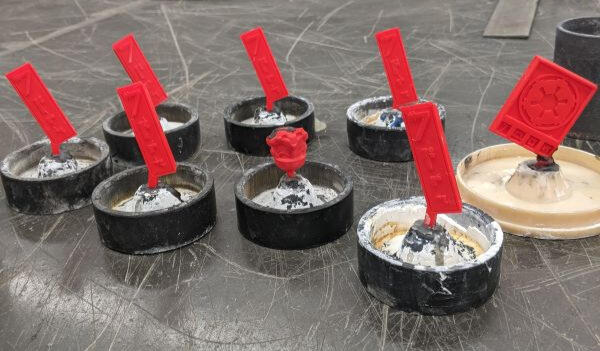
We ended up buying some new steel tubing to make the molds (wow metal is expensive!) and filled them up with investment. It took a while to figure out the right method for making sure the investment dries without cracking, but we eventually got it working well.Once the investment dried, I put the molds upside down into a kiln to heat up the investment and burn out the PLA. We followed the exact same temperatures and steps as we would with wax, which means this can be a pretty much plug and play solution for an existing lost wax casting setup.Because I had 3D models of the parts, calculating the volume of brass I needed was very easy. If I knew how much volume I needed, and I knew the weight of brass per volume, I could figure out the weight of brass I needed. I made sure to get those ready while the molds were heating.When the molds were at temperature and the PLA was burned out, I put on as much safety gear as I could find and moved one of the molds onto the centrifuge. I used the oxy-acetylene torch to heat up the brass, adding flux about half way through. Once the brass was liquid, I released the lock, letting the centrifuge spin and forced the brass into the mold.Once the centrifuge stopped spinning, I took the mold out and let the brass cool a little bit. Once it was almost solid, I quenched the mold in a bucket of water. The quenching process removes almost all of the investment which makes cleaning the part much easier.
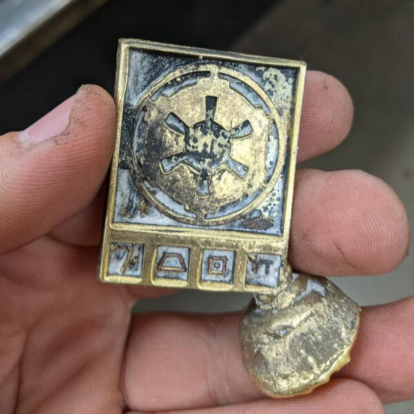
The last step was to cut off the sprue, do a bit of sanding, and clean off the slag and remaining investment. I used a hacksaw to remove most of the sprue and the stationary belt sander to clean up most of the edges. A fine wire brush did a very good job cleaning up the inside surfaces that couldn't be sanded.I'm not sure if I would introduce this to a class because molten metal spinning at high RPMs is not the safest, even with enough safety gear. If I was coming into a school that already lost wax casting and it was popular, I would probably bring in 3D printing to add that digital element and modernize the project.
Maple Keyboard Clock
Jan 14, 2021
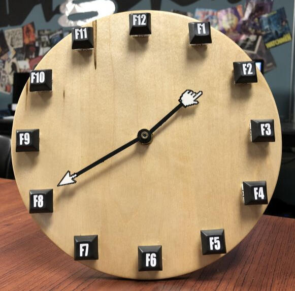
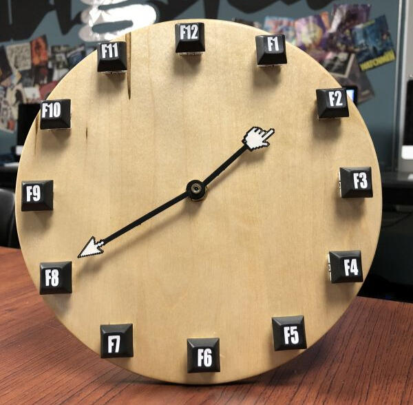
This was a birthday present for one of my more techy friends. The clock face is made of ambrosia maple and was cut out using a CNC wood router. The keys don't do anything but you can press them and they are real mechanical key switches (a must for any tech enthusiast). The movement of the clock is a simple quarts movement kit from Lee Valley. The numbers on the keys are sticker vinyl cut out with a Cricut vinyl cutter and the clock hands are custom 3D printed. In retrospect, I should have used the hourglass icon for the hour hand and included a second hand using one of the other cursors. Oh well, I want to try building this project again someday with working buttons so I can include all three hands then.
Live Edge Table with Butterfly Inlay
June 3, 2022

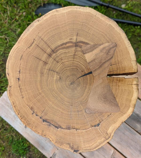
Out of all my personal projects so far this year, this table definitely taught me the most and I think turned out the best. This project arose from a perfect storm of coincidence where I happened to have access to a CNC router, a live edge cookie that was finished drying, and a friend getting married who needed a wedding gift.Like most of my projects these days, this one started with some 3D modeling. I knew I was working with the elm cookie, and I knew I wanted some sort of tripod legs. After fighting with the proportions for a few days, I had my design.
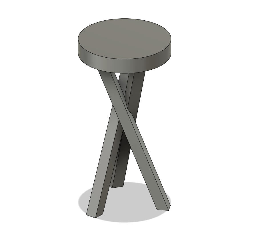
I've gotten pretty comfortable with Fusion 360 recently, so making the model was the easy part. Now I had to figure out how to generate g-code. Fusion 360 is great because I can design a part and generate the g-code all in one software, and most importantly, it's free!The first step was to flatten the cookie. Over the two years it was drying, it had started to bulge into a bit of a bowl shape, so I loaded a massive surfacing bit into the CNC and crossed my fingers that I got the feeds and speeds right. The massive surfacing bit probably wasn't the best bit to practice on, but hey, a trial by fire never burned anyone right?
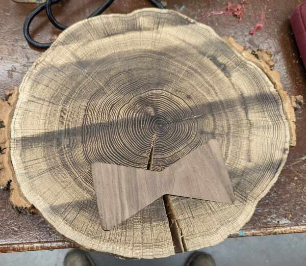
Now that I had a flat cookie, I needed to deal with the crack that had formed during the drying process. I had always wanted to try a butterfly inlay, and now was the perfect time to try one. Using a flat end mill, I cut out the pocket from the cookie. I cut the pocket all the way through, but in hindsight should have only gone halfway. It's not really an issue, but would have been more stable if I had done it correctly.
And a walnut inlay to fit the pocket!
I glued in the inlay and ran a few more surfacing passes to smooth everything out.
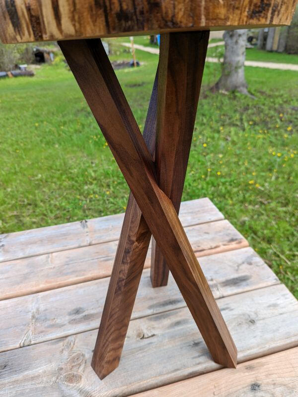
Now that I had some confidence generating toolpaths in Fusion, it was time for the most complicated part; the legs. I laminated some more walnut to create the 1 1/2" stock I needed and set to work figuring out how to cut them out. I ended up doing a rough pass with a large flat end mill, then a smoothing pass with a smaller ball end mill. There's a weird angle where the legs cross each other that I wanted to cut as accurately as possible and the ball end mill did a great job.
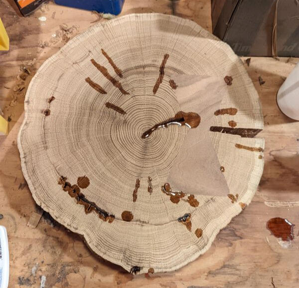
Last but not least used the CNC to create the joinery to attach the legs to the top. I then squared a few corners caused by the round bits with a hand chisel.In addition to the large crack that I fixed with the butterfly inlay, there were a bunch of smaller cracks that I wanted to stabilize, which gave me an excuse to try my hand at epoxy resin. I filled the cracks, popped the bubbles, and sanded away the excess once it dried.
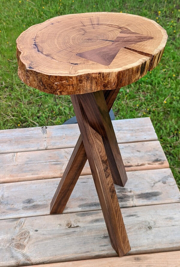
Now I could finally assemble the table. I had about a week before the wedding, so I was really glad that all the joints fit together well and the table sat level.

Since there were a lot of weird angles and corners, I decided to just use a spray can of semigloss finish. I've definitely gotten better at using spray finishes, and here's some final beauty shots to prove it.
CNC Logo Sign
Mar 28, 2022
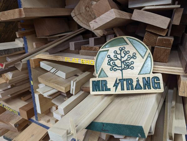
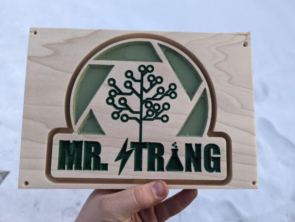
To get some experience using CNC routers in our electronics class, we made signs to hang in our future classrooms. You might recognize the logo from a certain website.We started by milling up some poplar blanks. Poplar machines pretty well but more importantly, we have a looot of it in the shop right now. In Aspire, we generated two toolpaths, one using an end mill to clear away lots of material quickly, then another pass with a V bit to add the detail.
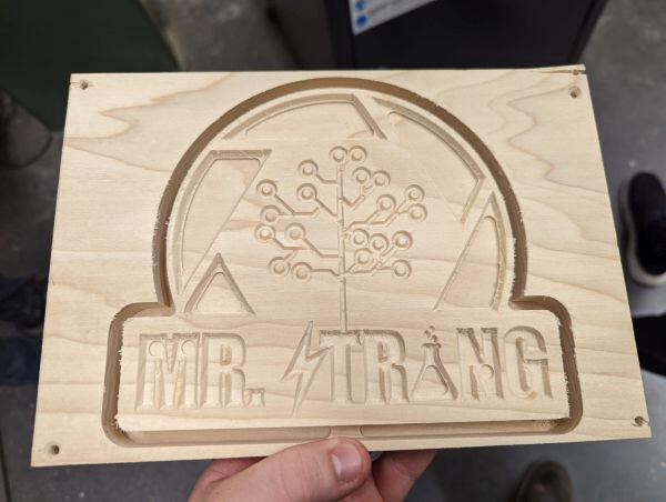
To add colour, I just added some cheap acrylic paint to the pockets, and sanded off the paint that splashed onto the top surface. I did this before cutting out the sign to help keep the top surface from rounding over during sanding.
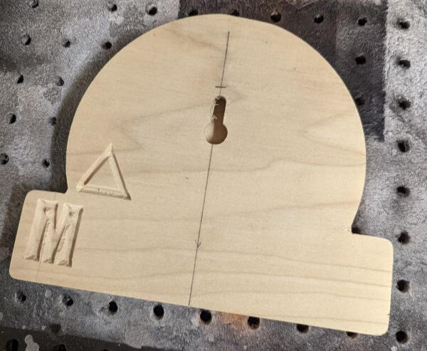
To hang the sign up, I used a keyhole bit in a plunge router to cut (you'll never guess this one) a keyhole! Then I cut out the final shape on the bandsaw and cleaned it up with a flush trim bit. In this picture you can also see the first failed attempt at running my toolpath.
The last step was to add some finish (I don't remember what but I have a habit of using Danish oil, so probably that). And voila, a sign for a classroom I don't have yet.
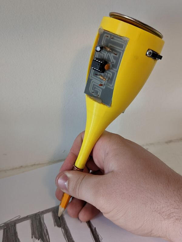
Drawdio
Mar 23, 2022

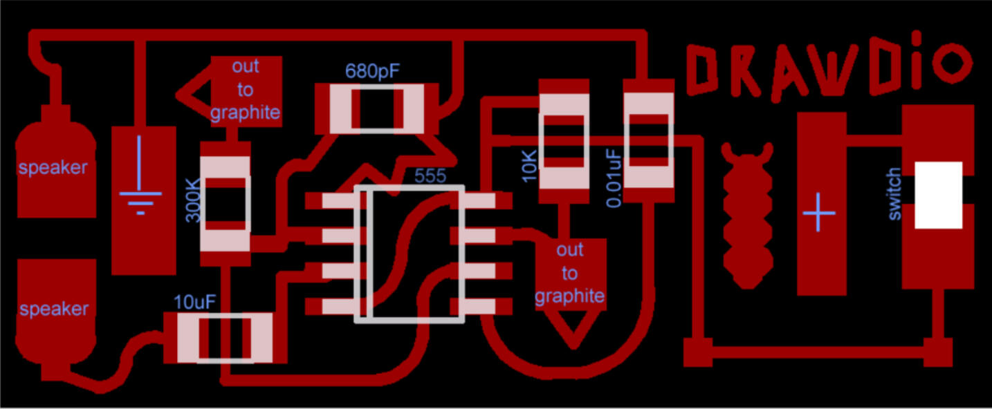
This was our major project for Electronics this year. Current runs through the user's body, then through graphite drawn on paper. When the current returns to the circuit board, a tone is played on the speaker depending on how much resistance is encountered in the graphite. More distance traveled through the graphite means more resistance, and therefore a lower tone.We started with a schematic from drawdio.com and machined a PCB to contain most of the components (which of course I forgot to film).
Other than building the circuit, the other part of the project was to design a housing to contain everything. I started by making rough 3D models of the parts, and arranging them together as tightly as possible.
Next I created a shape to contain everything and cut out holes for the components.
After some soldering and assembly that I forgot to document, I had a working Drawdio!
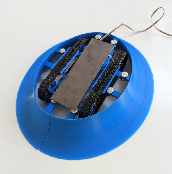
Sumo-Bot
Mar 1, 2022
The second project for my STEM class was the SumoBot. I built one in grade 8 using the same gearbox so I decided I needed to challenge myself. Since good grip is important, I decided to try making tank treads, which would have more surface area touching the ground than wheels.First I designed one of the links of the tread, which ended up being very similar to a watch band. After a few iterations, I got the links to fit together using finishing nails for the joints.
Next I needed to design the chassis that would hold the gearbox and keep the treads tight. The first one didn't really work. It wasn't designed to work well with 3D printing and had a lot of support material. The front axel also bent quite a bit so the treads didn't stay on properly.
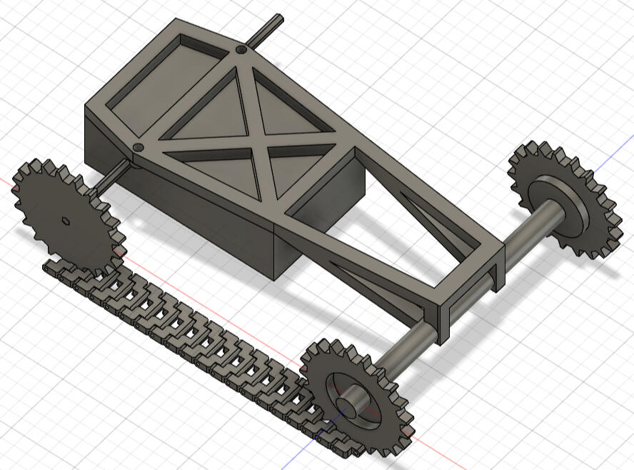
I redesigned the chassis to print flat and reinforced the front axel. I also shortened the teeth on the gears so they would mesh with the treads more reliably.
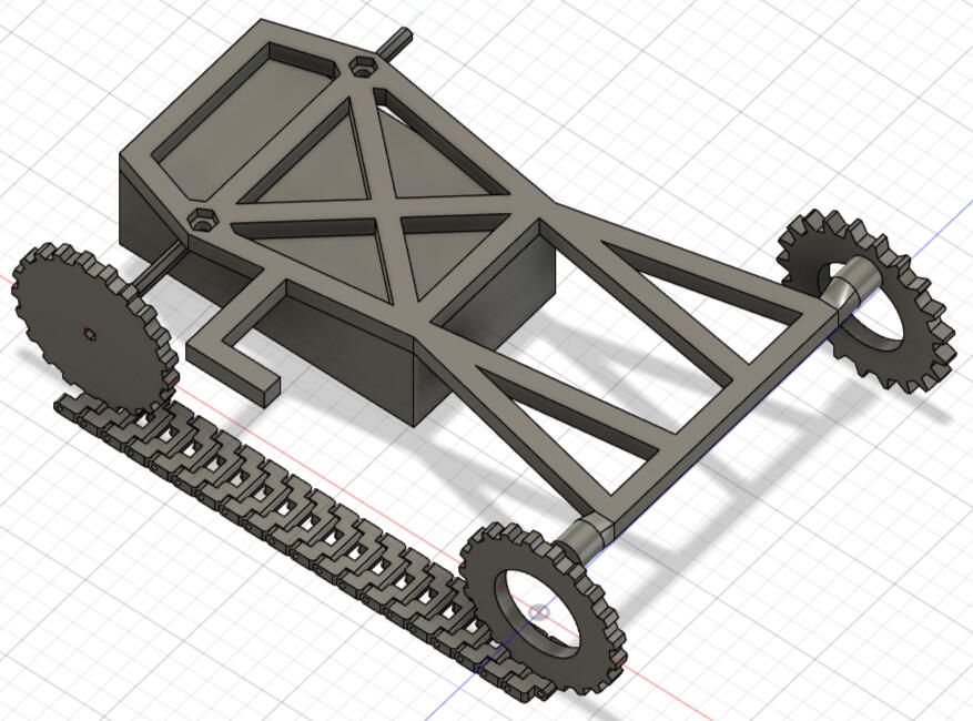
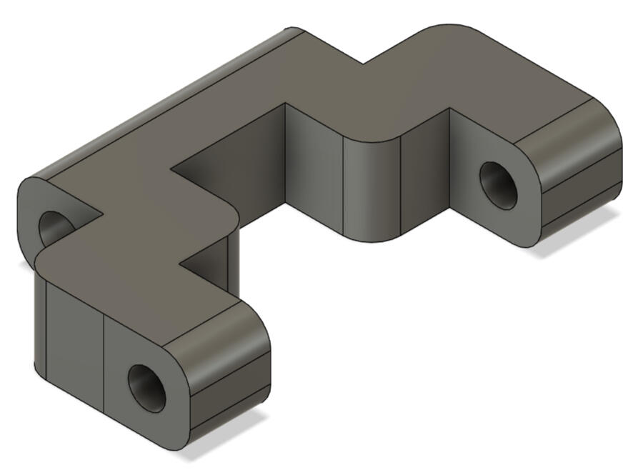
The next issue I ran into was keeping the treads running straight. When there was any sideways force on the treads they would fly off, so I added some guides that worked really well. In this iteration I also added a spot to thread the wires through so they wouldn't get pulled off the motors during battle.
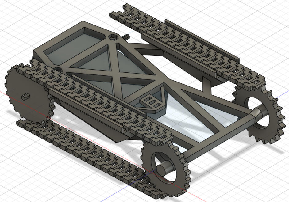
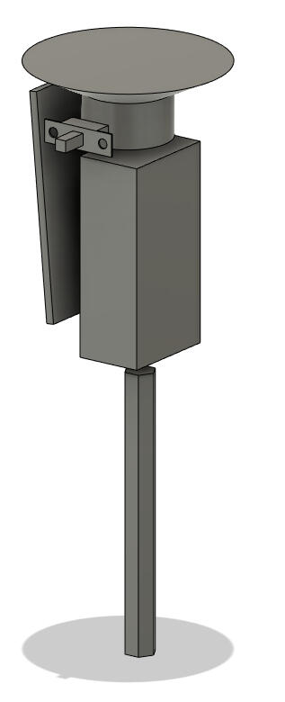
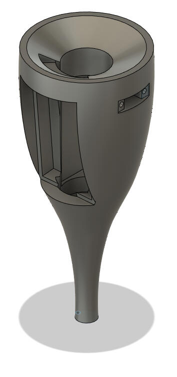
The last challenge to tackle was the ramp. The most important part of designing a sumobot is finding a way to get underneath the opponent, getting their wheels off the ground and pushing them out of the ring or flipping them over. I chose to assemble my gearbox for torque, instead of speed, so I knew a faster bot could get behind me pretty easily. I designed the scoop to wrap around my entire bot to protect me from all angles. Because the competition had the bots starting back to back, I had the added benefit of not needing to turn around, because my scoop was also on the back.
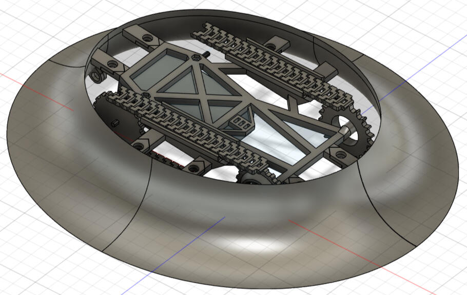
My final modification was to increase the weight of my bot right up to the weight limit with a steel plate.In the end my bot wasn't the overall winner but I got a joint second with two other competitors. My scoop wasn't as flush to the ground as I would have liked, but fixing that would have been a trade-off for my treads to grip.
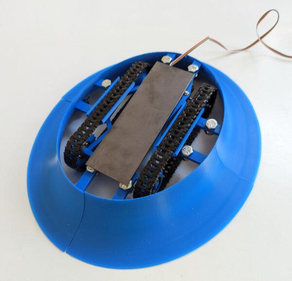
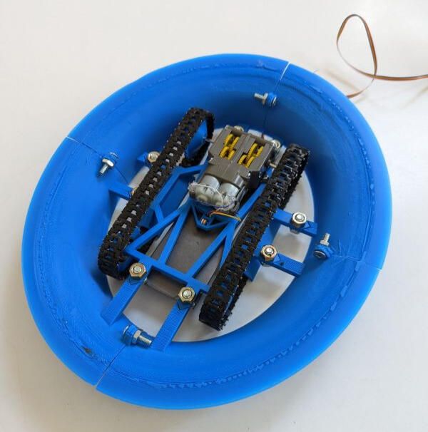
To close off, here's a shot of the bottom of the bot, since I took the picture and haven't put it anywhere else in this post.
Mousetrap Car
Jan 25, 2022

This was the first project for this year's STEM class. It's apparently a pretty common project in physics class but we didn't do many projects in high school physics.The goal is to travel the farthest distance, using only the power of a single mouse trap. They key is keeping the car moving slowly, spreading out the use of energy and reducing the amount of energy lost to friction and acceleration.I wanted to try something a bit more complicated than a simple mouse trap car to challenge myself, and my first idea was to use a pully. This would increase the mechanical advantage, which is already increased by the lever arm attached to the mouse trap spring. The world record mouse trap car used a pully so I figured building a pully myself would work well.
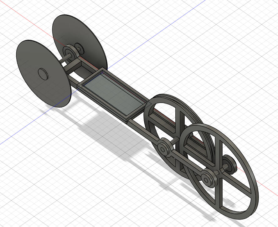
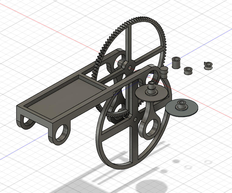
My first design never made it from the virtual world into the real world, because I realized the pully would have dragged on the ground. I also remembered that Fusion 360, the software I used to 3D model my mousetrap car, has a tool to make gears. Unlike a pully, I wouldn't have to tension gears as long as I spaced the axels properly.
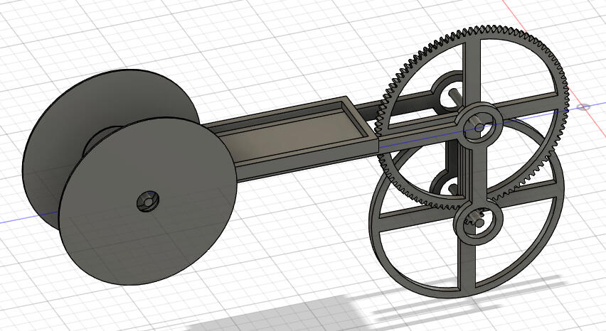
In my second design, I moved the driven axel below the drive axel to keep the big gear off the ground. I also think it looks cooler this way.
The second design made it into the real world, with mostly laser cut components, save for the tray holding the mouse trap.
This design worked pretty well, except it didn't run straight. The most likely cause was that the front and back axels weren't parallel, which I thought was probably because the main body was made up of several different parts.
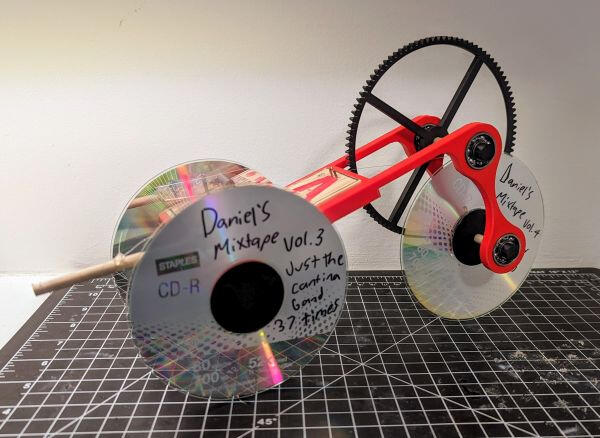
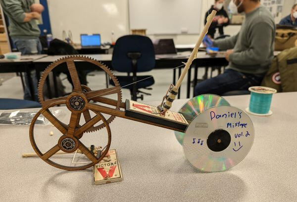
For my third version, I got a bit lazy and didn't assemble the 3D model, but I made several improvements to the design. The main improvement was that the entire body was a single 3D printed piece. This was a bit of a challenge because the bed of my 3D printer isn't very big, but I managed to make everything compact enough to fit. I also improved the spool that winds the fishing line on the drive axel, and replaced the back wheel with a CD (but apparently didn't save it on Fusion).
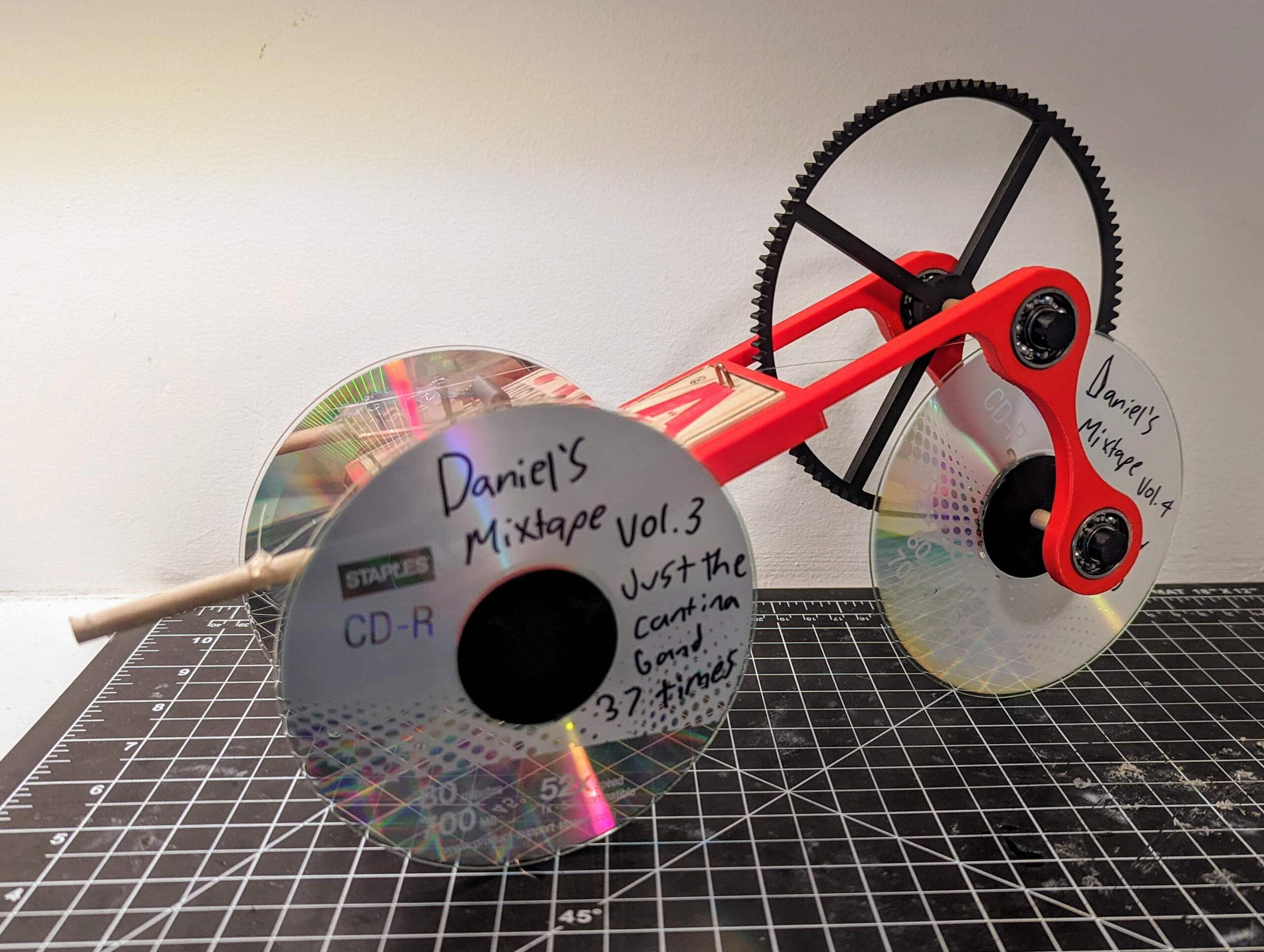
This car ran straighter at first, but on the day of the test I managed to drop it not once, but twice so that was the end of that. I'm still happy with the car's performance and at some point maybe I'll fix the bent wheels and see how far this thing can really go.
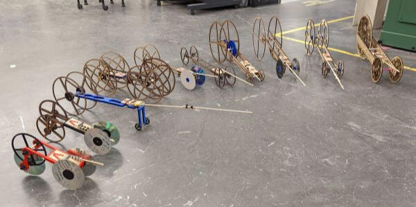
Here's all 10 cars built by my class for this project. The winning car was built by Alex and is third from the right.
Longboard
Oct 26, 2021

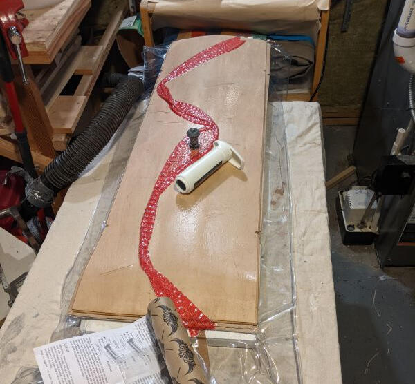
This project has been on my radar since grade 11 when I saw some other students make them in class. It was a bit of an investment to buy the tools but I really enjoyed the process and I'll hopefully be able to use the equipment with students in the future.The first step was to glue up the veneer using a vacuum bag to press the layers onto a Styrofoam form. The kit I bought came with a pre-shaped form, as well as laser engraved designs for the board itself. The engraved designs were nice because this was my first board. If I make any boards for myself in the future, I'll probably make my own pattern. I also could have carved the form out of foam insulation but it makes a huge mess.
Once the board was glued up, it was time to cut it out. I was able to fit the board onto my tiny bandsaw at home, which made the process faster. It is also possible to do the same thing with a Jigsaw, but the bandsaw is safer in my opinion, especially for younger students.Once the board was roughly cut out, I used a shaver to get the board to it's finished shape. I also used a special card scraper to add the round over on the edges. This could have been done with a router but I do not own one. Using the card scraper does take much longer but it's much cheaper to have many of them so if there were several students working on boards, the timing might work out.
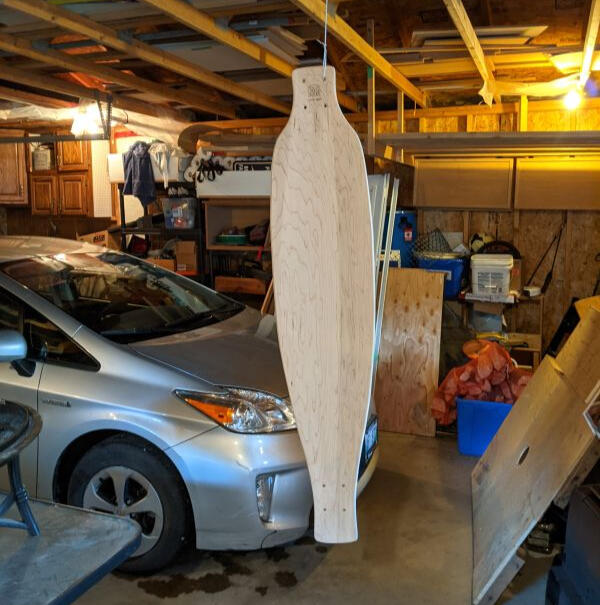
Next up was drilling the holes for the trucks. The laser engraved templates had pre-marked holes for the trucks. It turned out that the holes didn't quite line up with the trucks I bought, so that made assembly take much longer. Once the holes were drilled, I hung the board up in my garage and sprayed on a few layers of finish.Once the finish was dry, I stuck on the grip tape and spent a while trimming it to the edge of the board. The best method I found was to use a knife to roughly cut away the extra grip, then use a file to shave it down right to the edge of the board.
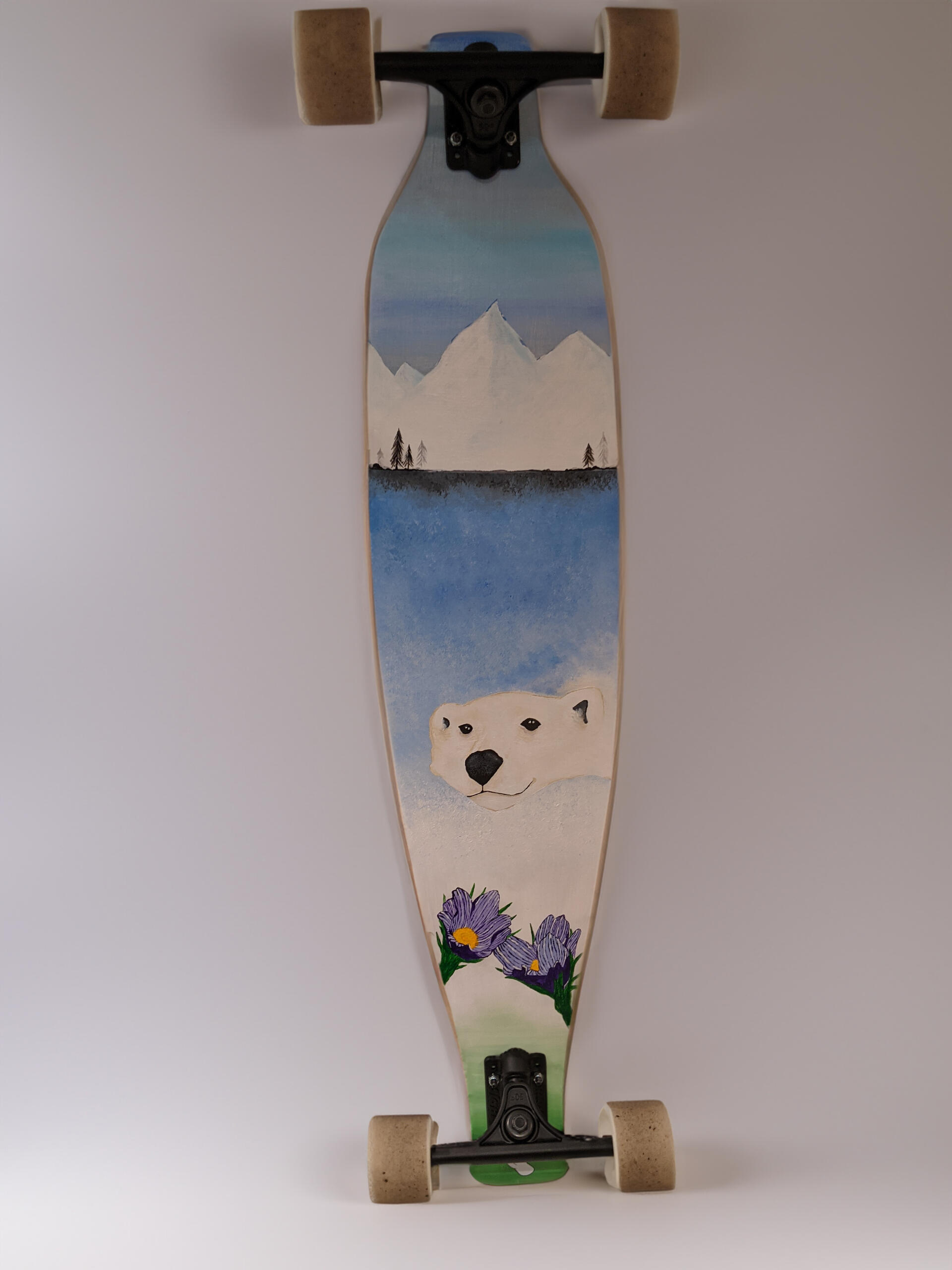
Finally, I handed the board off to my friend Rae (@brain.f.arts on Instagram) to add the fantastic paint job!
Stained Glass Lily
Oct 21, 2021

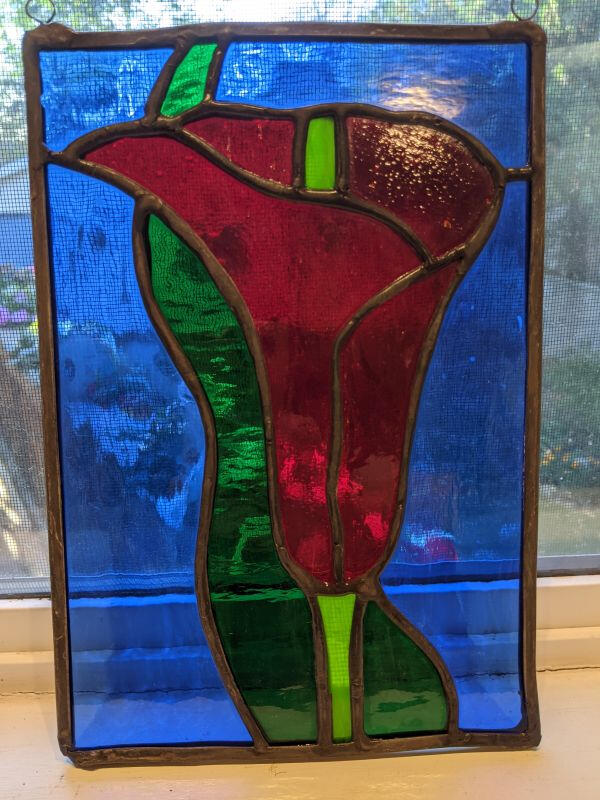
My first time working with stained glass was when I was about 14. My mom and I took some introductory classes at Prairie Studio Glass (then called Prairie Stained Glass) and I made quite a few panels. A number of them are still hanging at home, reminding me how bad my soldering was back then.This year in my Manufacturing class, one of the assignments was to develop a project aimed at middle school students. Because of the pandemic, as well as shorter than normal classes all year, I looked for a project that I could do at home. Luckily for me, my mom has continued on with stained glass so we had all the equipment at home.This pattern was one that is often used in beginner courses at Prairie Studio Glass. It has easy curves to cut and not too many pieces. The first step was to cut the glass using a diamond wheel cutter. I had to do plenty of practice cuts to get the hang of using the cutter again but eventually I was able to cut everything accurately.
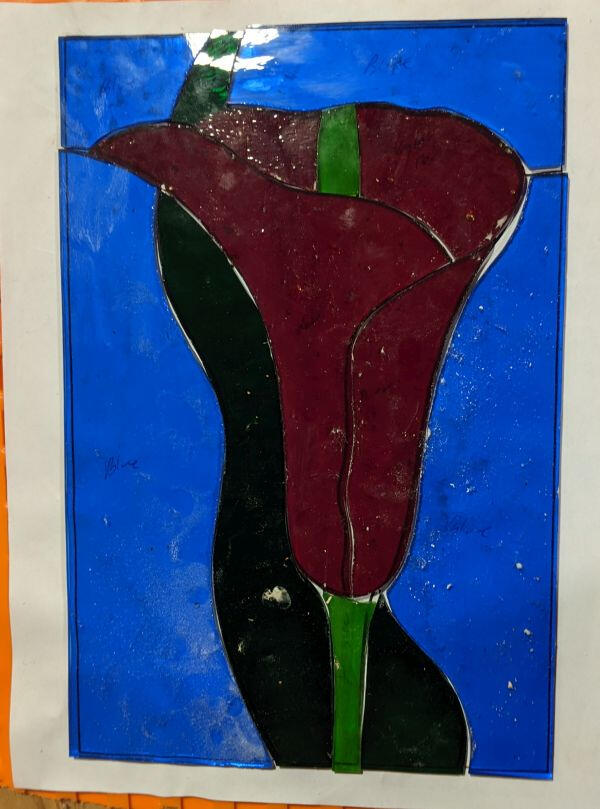
Next up was grinding. The glass doesn't always break at exactly 90 degrees, and some curves are difficult to cut, so I used a diamond grinder to get everything to final shape. The grinder is basically a tiny spindle sander, but it has a water reservoir to keep the glass dust out of the air.Once all the pieces fit together properly, it was time to add copper foil tape. Solder won't stick to glass on it's own, so the foil tape helps keep the solder where it needs to be.
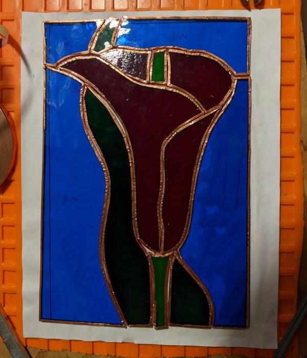
After foiling and soldering some practice pieces, it was time to get everything soldered together. All of the inner joints went together pretty easily, although I'll need to be more careful about avoiding gaps next time I cut glass. The most difficult part for me was attaching the lead C-channel border to the edges. Because it's made of lead, the C-channel is very malleable, and stretchy, which can be used to help keep the panel together. Before attaching the C-channel, I put one end in the vice and pulled the other end. Once the C-channel is attached to the panel, it will slowly contract, pulling the panel tight. Soldering the corners of the C-channel together and making any other joints was difficult, and it's something I'll definitely have to practice.
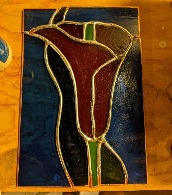
After soldering on the loops to hang the panel, the last step was to apply patina. This turns the solder from silver to black (or sometimes copper, but not in this case). I think my container of patina was old because it didn't work as well as I was hoping. Even after a few applications, the solder wasn't as dark as it could have been.I'm happy to report that my soldering skills have improved since I was 14, but there's still plenty of room for me to improve yet.
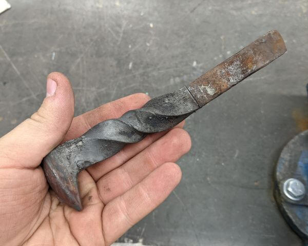
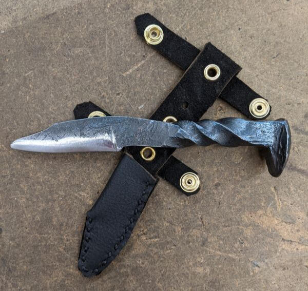
Railroad Spike Knife
May 27, 2021

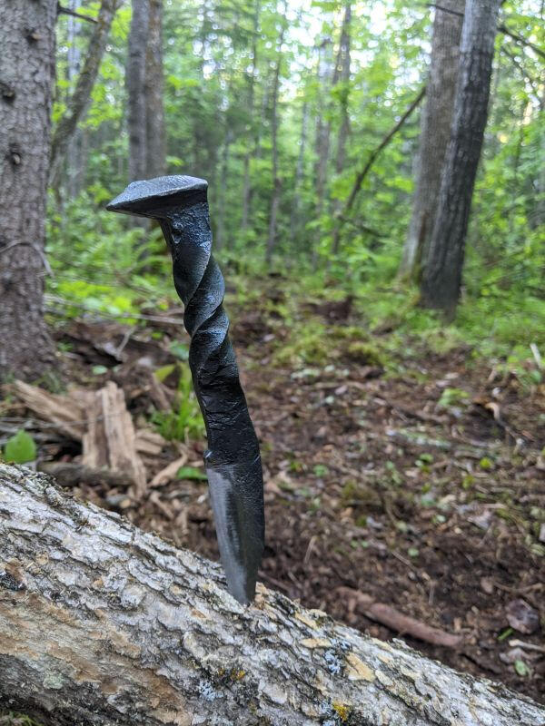
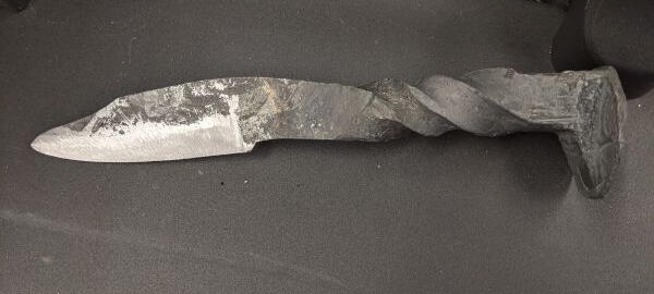
I've always wanted to take a stab (get it?) at knife making. When one of my classmates made one out of a railroad spike, I knew I had to try it for myself.I decided to focus on the handle first. According to my research, there's a pretty even split between people who do the handle first, and people who do the blade first. Twisting the handle first lets you make sure the handle is long enough for your hand, but you risk damaging it while making the blade. I put the blade end in the vise and used the oxyacetylene torch to heat up the handle. Then I grabbed on with vise grips and slowly twisted. It was difficult to keep the handle hot enough while twisting it, so my cooperating teacher used the torch to keep it at the right temperature.
Now it was time to draw out the blade. This was difficult because I didn't have a proper forge. We used the casting furnace, which just barely got the piece up to a workable temperature. I could only get a few hits in with the hammer before the blade cooled down too much. Then it was back in the furnace for about 10 minutes to heat up again. It was a long process and the blade is thicker than I would have liked but considering the tools I had available, it turned out pretty well.
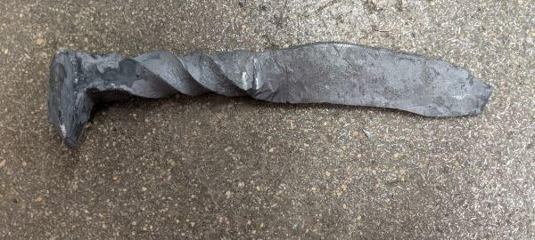
Next I used the stationary belt sander to grind down the profile of the blade. Then I sketched the blade bevel onto the piece.
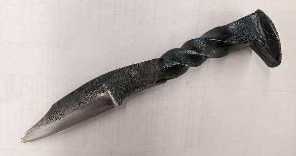
To add the blade bevel, it was time to file. I probably could have used the belt sander to get most of this work done, but it is much easier to ruin the blade if I slip up. Another challenge was finding a good way to hold the knife in the vise so that I could use the full length of the file at the right angle. I managed to figure it out and got the bevel sharp enough to move on to the next step.
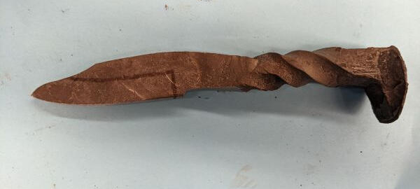
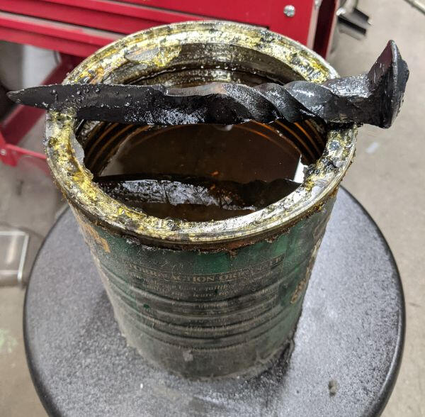
Now I needed to quench the blade to harden the steel. The steel that railroad spikes are made of doesn't have a high enough carbon content to form a very good blade so it won't be an incredible knife. This specific spike had an H cast onto the head, which means it has high carbon for a railroad spike, but not high carbon compared to proper tool steel. I used the casting oven again to heat the knife up to temperature. When it was glowing the right colour, I quickly submerged it in quenching oil and let it cool off.
he last step was to clean up the bevel and sharpen the blade. I wanted the bevel to be bare metal, so I needed to file off the bluing from the quenching process. Then I spent quite a while filing down the edge to get it as sharp as possible. It's not the sharpest knife I've ever seen, but it's sharp enough to be called a knife at least.
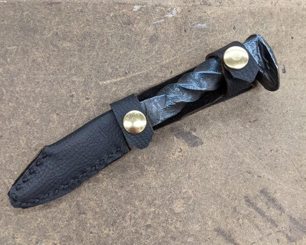
As a bonus, I decided to make a leather sheath. My leatherwork skills are pretty lacking and I'm not super happy with the final sheath but it does the job well enough. The handle of the knife is very heavy compared to the blade which made designing the sheath a bit tricky. I'll definitely be making a new sheath at some point so stay tuned!
Leather Trapper Hat
May 23, 2021
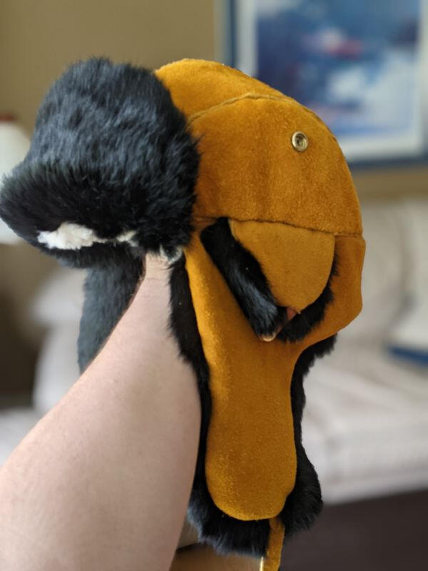
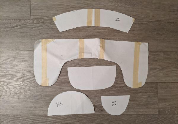
This was my sixth foray into working with elk leather, and my first time making a hat. My previous winter hat was a similar Ushanka (the Russian name for this type of hat), but a cheap store bought version that was falling apart. As the COVID-19 pandemic began, I thought I would need projects to keep myself occupied so I decided I would make my own replacement hat.The first step was to create a pattern, which was a process of trial and error. Referencing my old hat, I traced and cut out the different parts of the hat. Then I cut out the parts in cheap fabric and loosely sewed them together. This helped me figure out what parts of the pattern needed to be bigger or smaller. After going back and forth a few times, making new paper patterns and fabric pieces, I finally had a design that would fit.
I used the pattern to cut out the final pieces from elk leather, rabbit fur, and a synthetic wool for the inside liner. Elk leather is nice to work with because it can be cut with normal household scissors very easily.I used a thin strip of leather between the seam to hide my stitching and a thick thread to make sure everything was durable. Everything was sewn inside out, and in individual parts before assembling the whole hat.I decided to steal the chin strap hardware from the original hat, which meant I had to go hunting for snaps that would fit. I found some snaps at a fabric store that worked well. I also tried to use those snaps for the ear and forehead flaps but they were designed for fabric, so some of them fell off pretty quickly. This meant I had to take most of the hat apart and add proper leather snaps. These gave me issues as well, because they were designed for thicker cow leather. I ended up cutting tiny spacers out of cow leather to put inside the hat, which worked pretty well.After putting the hat together for a second time, I've got a final product that makes me wish it was winter.
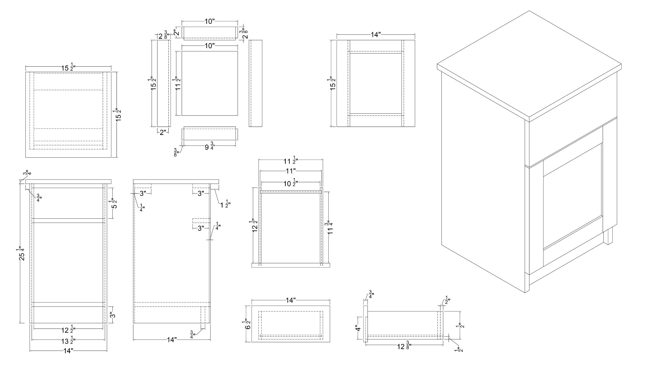
Nightstand With Secret Drawer
Dec 1, 2021

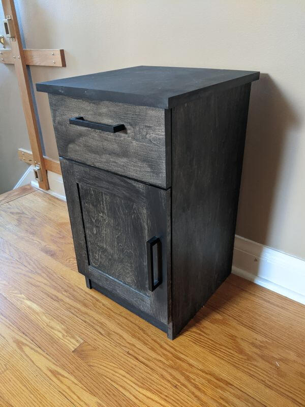
This was the major project for my 3rd year manufacturing class. I hadn't done cabinetry in a while and this was my first time making drawers.The first step was to draft a plan and figure out my measurements. We were given fixed final dimensions and specific materials to use so this was pretty easy.
The carcass went together pretty quickly thanks to a combination of simple dados and pocket holes.The drawer was a bit more complicated because we used a dovetail bit on the router to join the drawer front to the rest of the drawer.
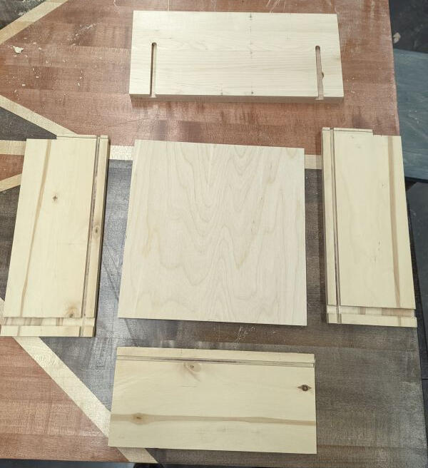
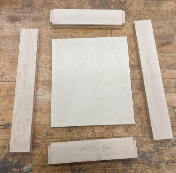
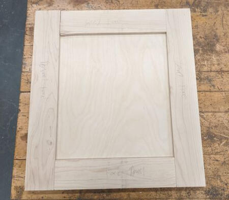
Like the drawer, the door involved a lot of router and table saw work to get everything assembled.
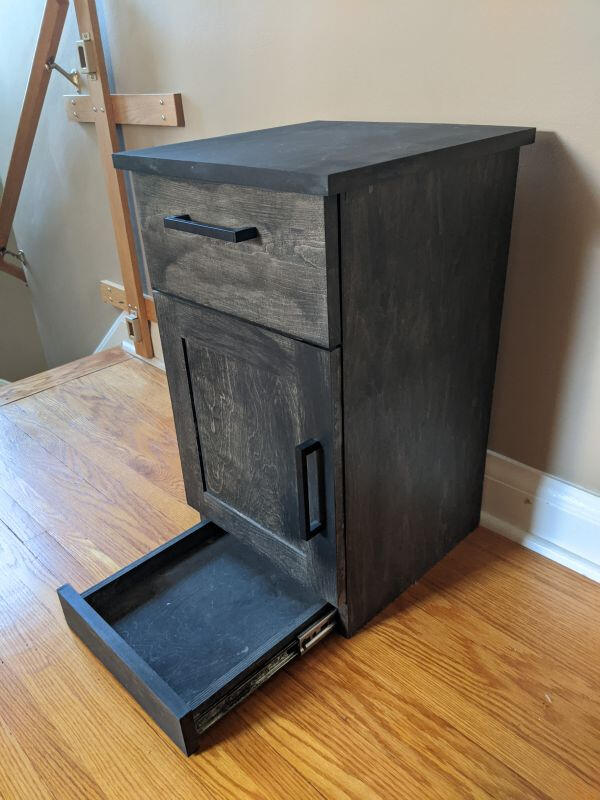
To add a bit more interest to the project, I decided to add a secret drawer behind the toekick. That went together the same way as the top drawer.
Once the drawer and door hardware was installed, all that was left to do was apply finish and donate my previous IKEA nightstand.
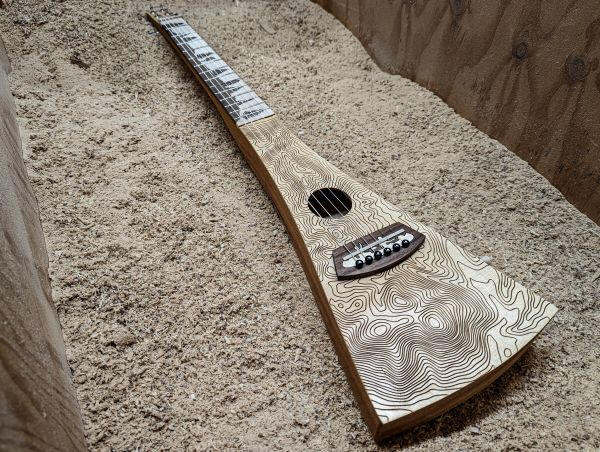
Backpacker Guitar
Dec 2, 2022
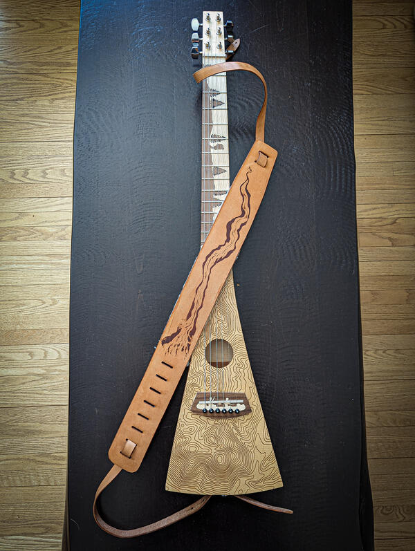
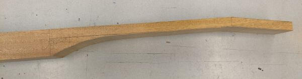
This was the big one, the project I've been looking forward to since the start of my program at the college.This project was easily one of the most challenging projects I've ever done, but I learned so much and it was an absolute blast! Buckle up, this is gonna be a long one.The first step was to mill the piece of mahogany that would become the neck and side walls. Once it was cut to size, I used the tablesaw to cut out what would become the hollow centre of the body.
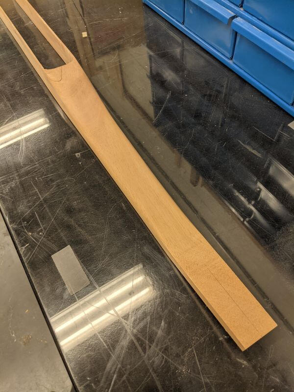
Next I cut out the rough shape of the neck on the bandsaw.
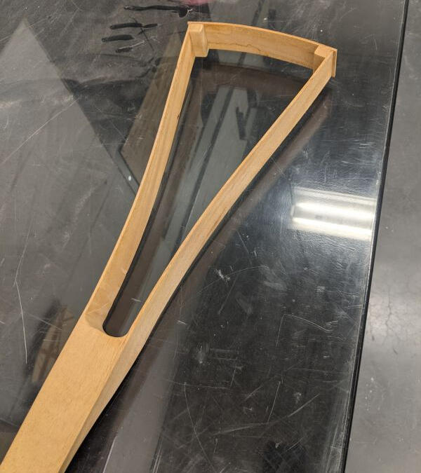
Lucky for us, another class was participating in a canoe paddle workshop, so we had some fantastic shaping tools available to us to shape the neck.
Now comes one of the coolest parts of the project; steam bending! I heated up the wood using steam, softening the lignin in the wood enough that the thin strips could be bent and clamped into a jig to cool. At the same time, I also bent the piece that would become the bottom (or top?) of the body using the same technique.
Once everything was out of the jig, I glued the sides of the body together, adding some blocks in the corner for extra support.
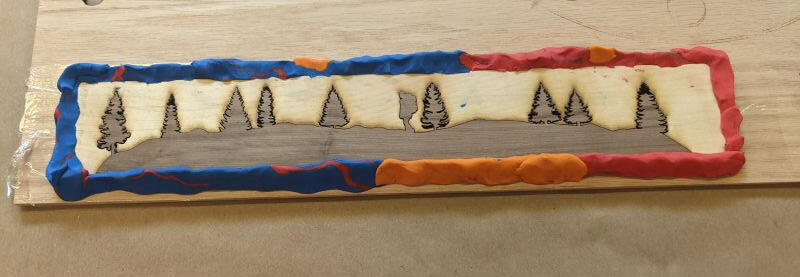
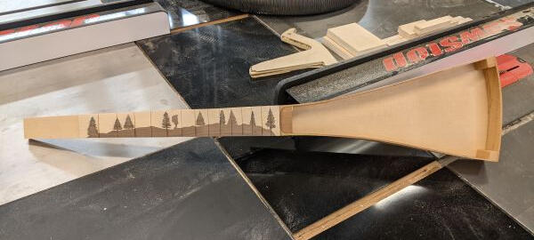
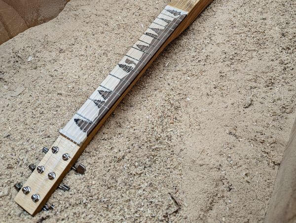
Next it was time to start working on the fretboard. I used the laser to cut a hiking scene inlay into strips of walnut and maple.
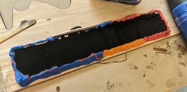
I got the suggestion to try using plasticine to make a mold around the fretboard for the epoxy. This worked ok for this small project but took a while to clean up after the pour. Speaking of the pour, I definitely used too much epoxy. My original idea was to keep a layer of epoxy below the fretboard, adding a stripe of black between the fretboard and neck. This chipped off pretty quickly when I was cleaning it up, so I scrapped that idea.
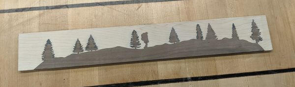
I took advantage of the laser's fantastic accuracy to mark out the locations for the frets. Then the fretboard was ready to install!
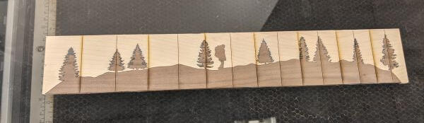
When I glued the fretboard onto the neck, I mostly just eyeballed its placement. In hindsight this was pretty reckless considering how much work had gone into the guitar by this point, but it turned out fine in the end. Once the fretboard was installed, I trimmed it down on the bandsaw, then used hand tools to bring it down to its final size.
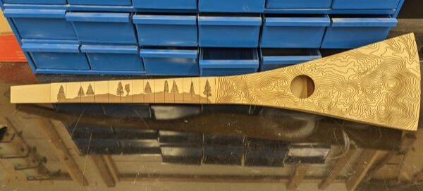
Now on to the soundboards. These were made out of Sitka Spruce and had topographic lines engraved on the front. I took a time-lapse of it but can't find it anywhere. So here's the finished engraving already installed.
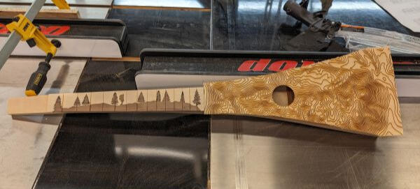
After a trim and some light sanding, everything looked great!
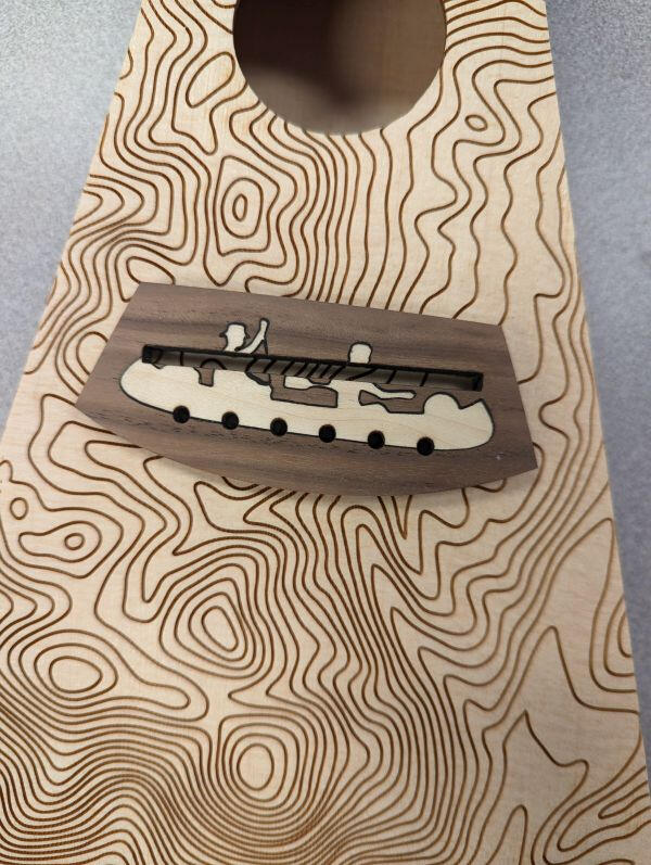
The last major piece to make was the bridge. Once again I used the laser to cut a maple inlay of a canoe to fit into the walnut bridge. Once everything was glued together with CA glue, it went back in the laser to cut out the holes for the bridge pins and the slot for the saddle, which had to be at a precise angle.
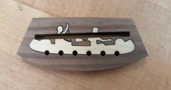
Once again I decided to mostly eyeball the placement of the bridge. Again it wasn't a good idea but it worked out in the end.
The last step of the build was to install the hardware. I managed to forget to take pictures of this process. I cut grooves into the fretboard and hammered in the frets, then didn't spend nearly enough time dressing them. The holes for the bridge pins were reamed out until the pins fit snugly. I drilled holes for the tuning pegs and installed them, and filed the nut to shape. After all that, I finished the guitar with Tru-Oil, a finish designed for gun stocks but that looks fantastic on guitars as well.
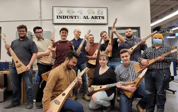
I'll also give a shoutout to the rest of my class and their guitars. This was such a collaborative effort and everyone's instruments turned out awesome! Bet you can't guess which two people are photoshopped into this picture.
A month later, I felt that the guitar was still missing something, and was looking for an opportunity to try leatherworking with the laser. I decided to design a simple leather guitar strap and I was really impressed with how well the laser handled the leather. The engraving on the main part of the strap was generated using the Dall E 2 ai image generator, which was just becoming popular at the time.

Plasma Cut Handsaw
Feb 1, 2023

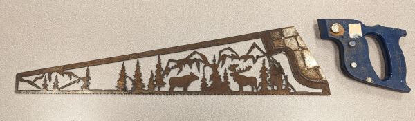
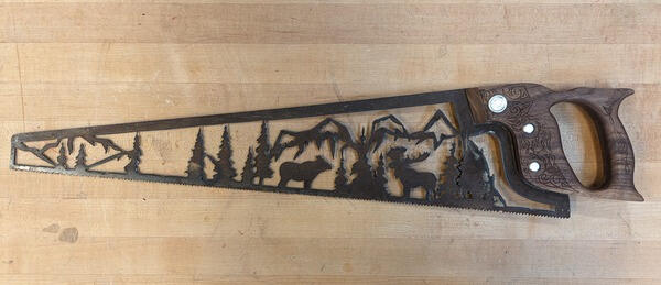
This project started because in my four years at the college, I hadn't used the CNC plasma cutter. I found this old Disston saw at a garage sale which sent me down a deep rabbit hole on saw restoration. Once I knew this saw wasn't one of the valuable ones, I could get to work drawing up the design in Illustrator.This was a pretty nerve wracking CNC operation because I only had one saw, so one chance to get it right. It took some problem solving to get it to stay in one place, but overall I think the cut went very well. I did loose one mountain on the left side though.
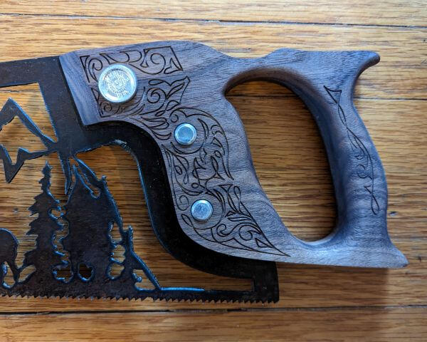
I protected the rust with a linseed oil based finish, and could have stopped the project there. The blade looked so nice that I decided to replace the plastic handle with a wooden replica. I modeled the handle in CAD and got to work carving it on the CNC router.I started by hogging out most of the design with a larger 1/8" bit, then came the challenging part of engraving with a bit that was only 0.008" wide. I managed to break one bit, which isn't too bad considering how my next CNC project went...
I had to make the handle in two sections because I didn't have thick enough walnut or a long enough CNC bit to cut it all at once. So the next step was to glue the two halves together and add a round over to make the handle more comfortable.
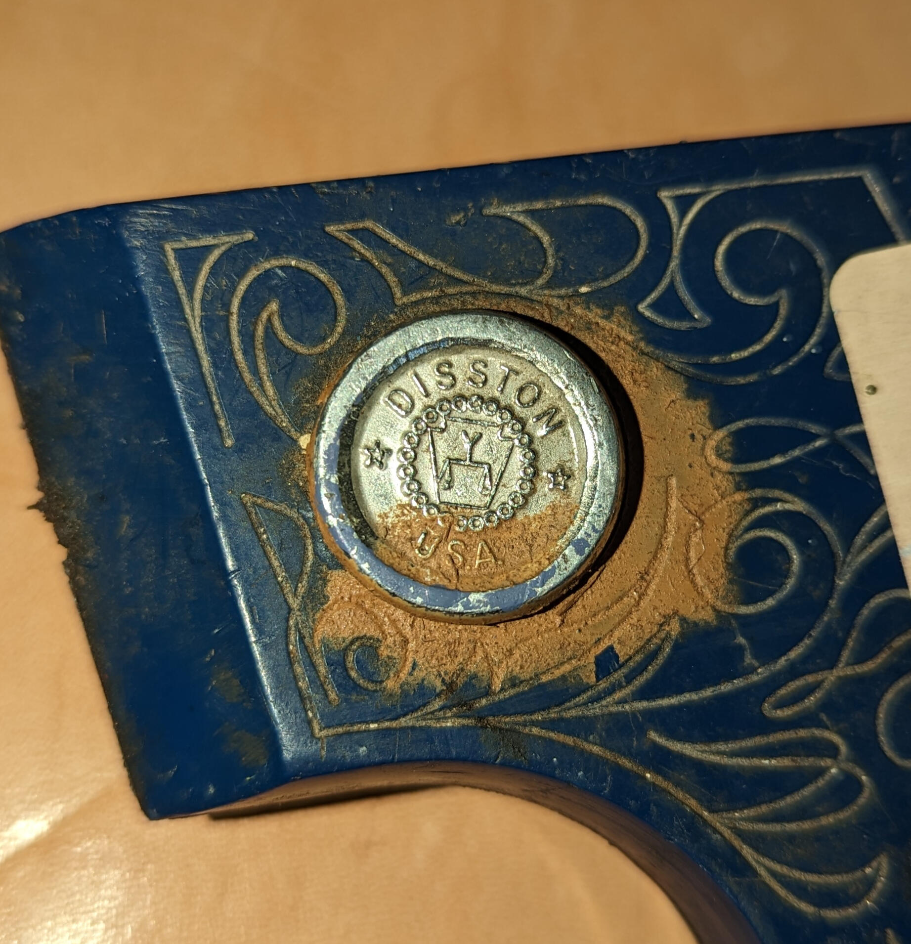
The saw came with some unique hardware that I wanted to include in the new handle. It started off pretty dirty but I was able to clean it up with an acid bath and a lot of polishing.
Overall I think this project turned out incredibly well! I hope I can get my hands on a plasma cutter again sometime soon.
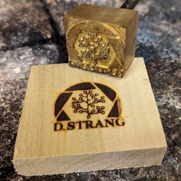
Branding Iron
Mar 1, 2023

I had been looking at buying a custom branding iron to mark my woodworking projects for a while. Then I remembered I'm paying huge amounts of tuition to a college that has the tools and materials to make my own.
Despite this being my first attempt at milling brass on the CNC, I decided to make my life more difficult by designing a very intricate brand. While I was able to clear away a good chunk of the material with a larger bit, I once again had to use a 0.008" bit to add the smallest details. I spent a lot of time calculating and re-calculating speeds and feeds for the CNC to stop the bits from breaking and eventually ended up with this:
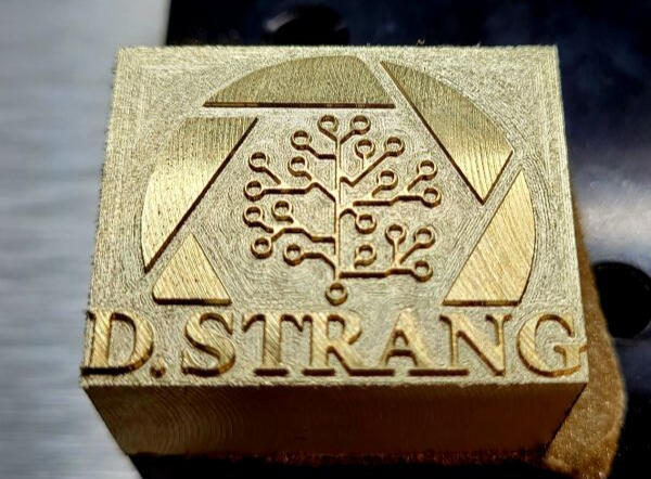
Now this looks great at first, but in the end it's only really useful as a fancy paperweight because I forgot to flip the design. Whoops!
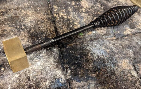
For my second attempt, I also decided to cut deeper so that I could make darker brands without hitting the bottom. I'm not totally sure this was necessary and it increased the machining time significantly. In total I think the CNC was running for about 12 hours.
I tried out the brand and it worked pretty well, so the last thing I needed to do was add a handle. At first I thought about making one on the lathe, but then realized a $10 welding hammer from princess auto had a handle that was the perfect size, so that's what I went with.
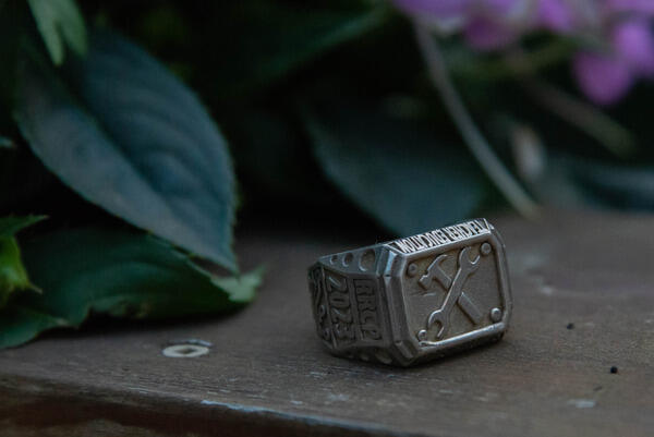
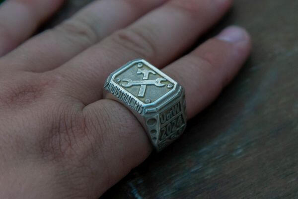
Grad Ring
Mar 29, 2023

I've been looking forward to this project since I started my program at the college, and especially after I did some brass casting at my first practicum. When I found out this project was being removed, I decided to incorporate it into my series of capstone projects, which also included the branding iron, handsaw, and guitar strap.
The first step was to create the 3D model. I didn't do this completely by scratch because I found a model online that I really liked. In hindsight, modelling from scratch probably would have been faster because I had a lot of trouble getting the model to cooperate with Fusion 360. I learned a lot about STEP files and different 3D tools in the process so it wasn't all bad.
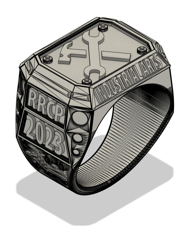
Like any good project, this was an opportunity to get myself a new tool. When the college used to make grad rings, they would use a CNC to carve them out of wax, which had a pretty high failure rate. Instead, I decided to buy a LCD resin 3D printer and print the rings in castable resin.
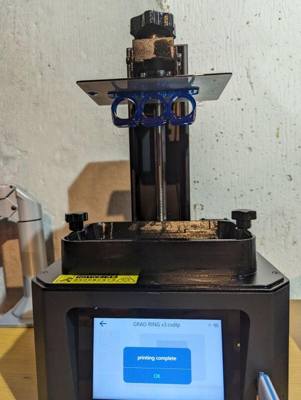
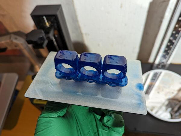
The prints had to be washed in a bath of isopropyl alcohol to get rid of the excess resin, then post-cured with UV light to finish the chemical reaction.
Now the rings could be reamed out to fit our fingers, and we could attach a sprue made of wax. The sprue could have been added to the 3D model but I didn't think of that until after.
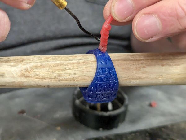
Now the sprue could be attached to a rubber base, then a metal cylinder placed around it to make the mold. Investment, which is a lot like plaster, was poured into the cylinder, then the whole thing went into a vacuum chamber to remove any bubbles.
Once the investment dried, the molds went into a 1200°F kiln to burn away the 3D printed resin, leaving a void shaped like the ring. I used an oxyacetylene torch to melt the silver into a crucible attached to a centrifuge. After adding some borax to act as flux, we transferred the molds from the kiln to the centrifuge and let the whole thing spin, forcing the molten silver into the mold. Once the silver solidified, the mold got dunked into some water, instantly cooling it down and breaking the investment away.
Next the ring could be sandblasted to remove any remaining investment and scale, and then it was on to polishing.
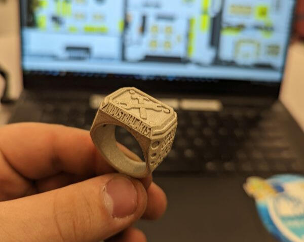
This took quite a while, and in hindsight sandblasting may not have been the best choice because the ring was smoother when it first came out of the mold. Once most of the ring was polished, I could cut off the sprue, file that down, and give everything one final shine. I couldn't be happier with how these turned out!


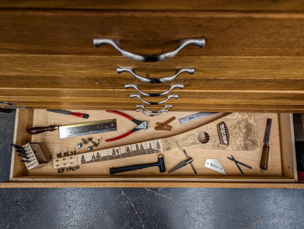
Filament Cabinet & Tool Panel
April 16, 2022
The more I've gotten into 3D printing,
Teaching Portfolio
Check out some of the teaching resources I have created!
Graphic Arts
I'm having some trouble getting the PDFs to load on mobile. If they aren't working just reload the page!
Photography Posters
This is a set of photography posters I created to display in a graphics classroom.
3D Printing Handouts
Here's a package of 3D printing handouts for any class wanting to implement 3D printing.
Everyday Spaceship Assignment
This is an assignment I created during my practicum at St. John's High School. It focuses on developing 3D modelling skills using Tinkercad.
How to make a vector pizza
When teaching students how to make vinyl stickers, I often found myself explaining that the process was similar to making a pizza. I created this guide with that analogy in mind.
Woodworking
I'm having some trouble getting the PDFs to load on mobile. If they aren't working just reload the page!
Safety Test Revitalization
In my fourth year at Red River College, I took part in an effort to re-imagine safety signage and tests in Manitoba Industrial Arts Classrooms. This was my design for a table saw safety test. This test focuses on testing students' understanding of how the machine functions, the hazards present, and how safety measures mitigate those hazards..
Bedside Cabinet Booklet
This is a booklet is a resource for the bedside cabinet woodworking project.
Planter Stand Project
This is a woodworking project I designed during my practicum block at St. John's High School. It covers a wide range of woodworking operations and has students using a variety of tools.
Here is a sample lesson plan from the planter stand project.
Drum Sander Maintenance
Maintenance of equipment is crucial for a well-running Industrial Arts Classroom. This is a resource I created to share with colleagues, detailing maintenance procedures for a common model of drum sander.
Metalworking
I'm having some trouble getting the PDFs to load on mobile. If they aren't working just reload the page!
Metalworking Portfolio
This is a portfolio of the metalworking projects I completed in my second year at Red River College
Metalworking Projects
These are plans for metalworking projects.
Facility re-design
This is my submission to re-design the Industrial Arts labs at Red River College. The re-designed labs separate woodworking, metalworking, electronics, and graphics into designated, but linked spaces to ensure safety while maximizing cross-curricular collaboration.
Electronics
I'm having some trouble getting the PDFs to load on mobile. If they aren't working just reload the page!
Electric Motor Lesson
This is a set of slides and lesson plan about electric motors.
CNC Course Proposal
I created this course proposal for a course that teaches the foundations of CNC technology and CAD design. This course is intended to provide the foundations for CNC projects throughout the industrial arts program.
Beetlebot Project
These are some handouts I created for the beetlebot project I ran during my Practicum in an electronics class at St. John's High School.
STEM
I'm having some trouble getting the PDFs to load on mobile. If they aren't working just reload the page!
Creating Controllers
This is an activity that I designed while working for Actua. It was presented at MTS PD Day 2022 to demonstrate how Industrial Arts teachers can incorporate STEM into their classrooms. It also showcased the Makey Makey, a piece of technology used to turn every day objects into computer keys.
Canoe Trip Curriculum
I designed this curriculum while working for Actua to be delivered throughout canoe expeditions in the Northwest Territories.
This is the Field Notebook that students received on the canoe trips.
Egg Drop Project
This is a egg drop project I created to be used in a science, physics, or STEM integrated Industrial Arts class.
Middle Years Lesson Plans
Here are some lesson plans I have created for middle years science.
Currently at pdf 21 for pdf api scripts